What is MIDI?
MIDI stands for Musical Instrument Digital Interface, a standard created for exchanging digital data between electronic musical instruments regardless of make and model. Thanks to MIDI, electronic musical instruments can communicate with each other and with computers at a level that was unimaginable twenty or so years ago. Without MIDI, recording musical events, programming mixers and the extensive use of computers in the recording studio, and on stage, would not be possible.
If you want to learn more about the world of MIDI, I recommend taking a look here.
Today, MIDI controllers are used not only for musical scoring but also as controllers for interacting directly with a machine or with software on a computer. Their applications have therefore extended to fields that previously had no need for them (for example, MIDI controllers are now built for medical use, for people who operate stage lighting rigs, for video mapping or, as in my case, for DJing).
Arduino… which one to choose?
As you can see directly on the Arduino website, there are many board models, from larger ones (with lots of inputs and outputs) to smaller ones, and some with wireless, Bluetooth connectivity and so on. Choosing the right board is actually very important, so first let’s work out what we want to build and then choose the board best suited to our needs.
Personally, since my Arduino project was to build a USB MIDI controller, I focused my search on the ATmega32u4 chip (used on the Arduino Leonardo). This chip is connected directly to the USB port, without going through serial converters, which means the USB interface can be programmed: you can make it appear to a computer as a keyboard, a mouse or a MIDI controller, depending on how it is programmed.
What controls do we need?
There is a huge range of controls we can connect to an Arduino, but essentially they come in only two types: analogue or digital.
An analogue signal can take any value (within a known range). Greatly simplified, you can think of all physical quantities measurable in the environment as “analogue”.
A digital signal can take only two states (High/Low, 1/0), corresponding to two conventional voltage levels (for example, 5V-0V). With a similar simplification, you can think of all the information exchanged between logic components (microprocessors, memory, network interfaces, displays…) as “digital”.
How is an analogue or digital signal interpreted?
For an analogue signal to be read and processed by Arduino, it must be sampled, i.e. converted into a sequence of bits expressing its amplitude.
A digital signal is immediately “readable” as soon as its level (High/Low) has been determined.
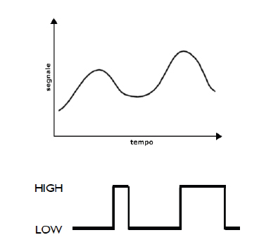
With an analogue signal, what matters is reading its instantaneous value, suitably sampled.
With a digital signal, all you need to know is whether it is high or low.
How does Arduino know whether a signal is an input or an output?
For Arduino to know whether a given pin carries an input or an output signal, digital pins must first be set to input or output mode. This is done with pinMode.
Example: pinMode(13, OUTPUT);
sets pin 13 to OUTPUT mode. This means a digital signal can be “output” from pin 13, which can therefore be High or Low. (In electronic terms, a voltage can be output that takes only two values, 5V or 0V.)
Example: pinMode(2, INPUT);
This example, on the other hand, sets pin 2 to INPUT mode. This means a digital signal can be “input” on pin 2, which, as in the previous case, must be High or Low.
Note that only digital pins need to be configured beforehand; analogue pins do not.
How do I read from or write to the pins?
Reading and writing are done through dedicated functions.
For digital pins we have:
digitalWrite() and digitalRead()
For analogue pins:
analogWrite() and analogRead()
Example of a digital “write”:
pinMode(13, OUTPUT); //Imposto il PIN 13 in modalità OUTPUT
digitalWrite(13, HIGH); //Scrivo sul PIN 13 il valore Alto
This code first sets pin 13 to OUTPUT mode (as seen earlier). It then “writes” a High value to the same pin.
Example of an analogue “read”:
int valore; //Dichiaro una variabile intera di nome "valore"
valore = analogRead(1); //Assegno alla variabile la lettura del PIN 1
This code declares an integer variable called “value”. It then assigns to it the analogue value “read” on analogue pin 1.
Where are the INPUT/OUTPUT pins on the Arduino Leonardo?
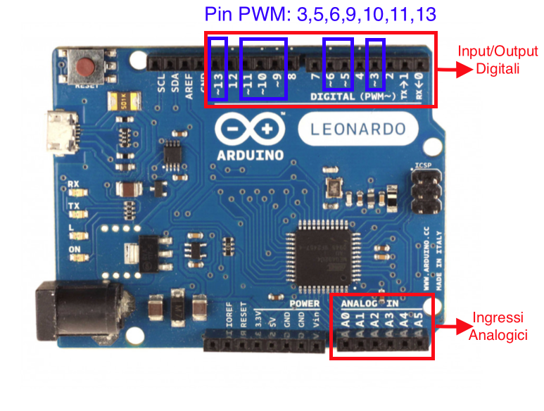
The difference between digital input and analogue input
- Unlike a digital input, which can take the two values LOW and HIGH, corresponding respectively to zero voltage (GND) or positive voltage (+5V), an analogue input can read voltages anywhere between 0 and +5V.
- The analogRead() function, as we saw in the previous example, takes as a parameter the number of the analogue pin to read and returns an integer, which is assigned to a variable.
The integer returned is between 0 and 1023. This means the incoming analogue signal is sampled with a resolution of 10 bits (2^10=1024); in other words, dividing the maximum voltage that can be applied to the input (+5V) by 1024 gives a unit of 4.9 mV (the maximum resolution expressed in volts).
Any quantity suitably converted into a voltage can be read by Arduino:
- Temperature: temperature sensor
- Rotation: potentiometer
- Light intensity: photoresistor
- Distance: infrared sensor
- Tilt: accelerometer
- …
With this introduction to Arduino pins out of the way, let’s get back to our MIDI controller.
The controls I chose to include are normally open “soft” push buttons and logarithmic potentiometers.
In the example below I used:
- 1 Arduino Leonardo
- 4 logarithmic potentiometers
- 4 normally open (soft) push buttons
- 4 x 1 kΩ resistors
Wiring
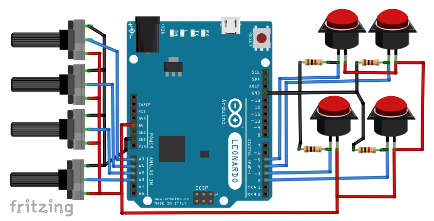
The 4 potentiometers are connected directly to analogue inputs A0, A1 A2 and A3 respectively.
Below is a detail of how a potentiometer is wired
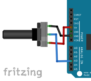
As you can see in the image above, the potentiometer needs three connections to work: starting from the bottom, the first goes to the Arduino’s 5V, the second to the analogue pin and the third to ground (GND).
The 4 buttons, on the other hand, are connected to digital pins D2, D3, D4 and D5 respectively, but to work correctly they need a resistor (to avoid “flickering” problems).
Below is a detail of how a “soft” or “momentary” button is wired.
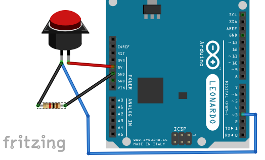
In this example you can see that one pin of the button goes directly to the Arduino’s 5V, while the second pin must be connected both to a 1 kΩ resistor, which in turn goes to ground, and to the digital pin that will receive the input.
Now that we have seen how to wire the potentiometers and buttons, we can start looking at the Arduino code step by step.
The libraries
#include <Bounce2.h>
#include "MIDIUSB.h"
The first library, <Bounce2.h>, is used to handle the buttons, while the second is used to enable MIDI mode (and all related functions) on the board.
Both libraries must be installed via the Arduino IDE’s Library Manager.
#define …
immediately after declaring the libraries, we define our pins by giving them simpler names, so that the code is easier to follow when writing or re-reading it
#define button1Pin 2
#define button2Pin 3
#define button3Pin 4
#define button4Pin 5
#define pot1Pin A0
#define pot2Pin A1
#define pot3Pin A2
#define pot4Pin A3
We also define our MIDI channel (channel 0 on the Arduino corresponds to MIDI channel 1)
#define CHANNEL 0
Declaring the variables
In this section I use arrays to hold the various notes that the buttons and potentiometers will send when they are used
int ButtonNote [4] = {60, 61, 62, 63};
int PotNote [4] = {17, 18, 19, 20};
In addition, again using arrays, I declare the button and potentiometer pins.
int ButtonPin [4] = {2, 3, 4, 5};
int PotPin [4] = {A0, A1, A2, A3};
now we need to define the Bounce objects for our buttons
Bounce Btn1 = Bounce(ButtonPin[0],5);
Bounce Btn2 = Bounce(ButtonPin[1],5);
Bounce Btn3 = Bounce(ButtonPin[2],5);
Bounce Btn4 = Bounce(ButtonPin[3],5);
and our potentiometers, plus variables to store the previously read value
uint8_t Pot1, Pot2, Pot3, Pot4, prevPot1, prevPot2, prevPot3, prevPot4;
void noteOn(), void noteOff() and void controlChange()
below are the three functions responsible for sending notes using the MIDI protocol via the Arduino board’s USB port
 void noteOn(byte channel, byte pitch, byte velocity) {
   midiEventPacket_t noteOn = {0x09, 0x90 | channel, pitch, velocity};
   MidiUSB.sendMIDI(noteOn);
   MidiUSB.flush();
 }
 void noteOff(byte channel, byte pitch, byte velocity) {
   midiEventPacket_t noteOff = {0x08, 0x80 | channel, pitch, velocity};
   MidiUSB.sendMIDI(noteOff);
   MidiUSB.flush();
 }
 void controlChange(byte channel, byte control, byte value) {
   // First parameter is the event type (0x0B = control change).
   // Second parameter is the event type, combined with the channel.
   // Third parameter is the control number number (0-119).
   // Fourth parameter is the control value (0-127).
   midiEventPacket_t event = {0x0B, 0xB0 | channel, control, value};
   MidiUSB.sendMIDI(event);
   MidiUSB.flush();
 }
void loop()…
The following is the portion of code that will be repeated indefinitely, until the Arduino board is switched off.
Essentially, it checks the 4 buttons, then checks the 4 potentiometers and finally calls the functions that send the notes
void loop() {
   Btn1.update();
   Btn2.update();
   Btn3.update();
   Btn4.update();
 Pot1 = map(analogRead(PotPin[0]), 0, 1023, 0, 127);
   if (prevPot1 != Pot1) {
     controlChange(CHANNEL, PotNote[0], Pot1);
     prevPot1 = Pot1;
   }
   Pot2 = map(analogRead(PotPin[1]), 0, 1023, 0, 127);
   if (prevPot2 != Pot2) {
     controlChange(CHANNEL, PotNote[1], Pot2);
     prevPot2 = Pot2;
   }
   Pot3 = map(analogRead(PotPin[2]), 0, 1023, 0, 127);
   if (prevPot3 != Pot3) {
     controlChange(CHANNEL, PotNote[2], Pot3);
     prevPot3 = Pot3;
   }
   Pot4 = map(analogRead(PotPin[3]), 0, 1023, 0, 127);
   if (prevPot4 != Pot4) {
     controlChange(CHANNEL, PotNote[3], Pot4);
     prevPot4 = Pot4;
   }
   if (Btn1.fallingEdge())
     noteOn(CHANNEL, ButtonNote[0], 127);
   else if (Btn1.risingEdge())
     noteOff(CHANNEL, ButtonNote[0], 0);
   else if (Btn2.fallingEdge())
     noteOn(CHANNEL, ButtonNote[1], 127);
   else if (Btn2.risingEdge())
     noteOff(CHANNEL, ButtonNote[1], 0);
   else if (Btn3.fallingEdge())
     noteOn(CHANNEL, ButtonNote[2], 127);
   else if (Btn3.risingEdge())
     noteOff(CHANNEL, ButtonNote[2], 0);
   else if (Btn4.fallingEdge())
     noteOn(CHANNEL, ButtonNote[3], 127);
   else if (Btn4.risingEdge())
     noteOff(CHANNEL, ButtonNote[3], 0);
 }
To download the complete code, click here
Enjoy!