What is Arduino?
As described on Wikipedia, Arduino is a hardware platform made up of a range of electronic boards equipped with a microcontroller. It was conceived and developed in 2005 by members of the Interaction Design Institute in Ivrea, Italy, as a tool for rapid prototyping and for hobby, educational and professional purposes.
With Arduino you can build small devices relatively quickly and easily, such as light controllers, motor speed controllers, light sensors, temperature and humidity control systems, and many other projects that use sensors, actuators and communication with other devices. It comes with a simple integrated development environment for programming the microcontroller. All the accompanying software is free, and the circuit diagrams are distributed as open hardware.
The software used to program these boards is called the Arduino IDE and is available free of charge directly from the manufacturer’s website (Arduino.cc)
What is a Wemos D1 mini board?
A Wemos D1 mini board is a miniature version of a NodeMCU. It is an open-source platform developed specifically for the IoT (Internet of Things). It includes firmware that runs on the ESP8266 Wi-Fi SoC and hardware based on the ESP-12 module, and it can be programmed in Lua or with the Arduino IDE.
How to program a Wemos D1 mini with the Arduino IDE
The first step is to download and install the CH340 driver so that your computer or Mac recognises the board’s serial port.
Once the driver has been downloaded and installed, download and then install the Arduino IDE on your machine.
Now download the hardware library https://github.com/esp8266/Arduino and copy it into the “hardware” folder, or alternatively launch the Arduino IDE, click File –> Preferences and add the following link http://arduino.esp8266.com/stable/package_esp8266com_index.json in the “Additional Boards Manager URLs” field
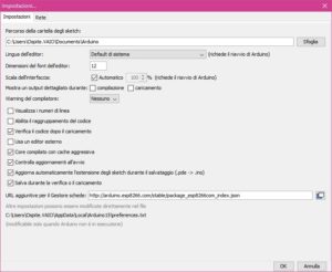
and apply the changes by clicking OK at the bottom right.
Now click Tools –> Board –> Boards Manager, and in the window that opens type ESP8266 in the search field (this is the chip mounted on the Wemos D1), then install it by clicking Install.
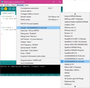
Next, click Tools –> Board again and you will see that ESP8266-based boards now appear; select “Generic ESP8266” or “Wemos D1”. Now click Tools –> Port and select the COM port your board is connected to.
The “Blink” example sketch
To start getting familiar with the board, it is a good idea to begin with the example sketches available directly in the Arduino IDE. (These sketches are added by the libraries you install in the program, as well as by the boards added via the Boards Manager.)
Click File –> Examples –> 01.Basics –> Blink
This is the basic sketch everyone started with.
Once uploaded to the board, this code simply makes the LED on the board blink (on for one second, then off for one second) — nothing particularly exciting, but by analysing the code we can understand how the board works and where we need to write/modify code to make it do what we want.
Let’s look at it in detail…
/*
   Blink
Turns an LED on for one second, then off for one second, repeatedly.
Most Arduinos have an on-board LED you can control. On the UNO, MEGA and ZERO
   it is attached to digital pin 13, on MKR1000 on pin 6. LED_BUILTIN is set to
   the correct LED pin independent of which board is used.
   If you want to know what pin the on-board LED is connected to on your Arduino
   model, check the Technical Specs of your board at:
   https://www.arduino.cc/en/Main/Products
modified 8 May 2014
by Scott Fitzgerald
   modified 2 Sep 2016
   by Arturo Guadalupi
   modified 8 Sep 2016
   by Colby Newman
This example code is in the public domain.
http://www.arduino.cc/en/Tutorial/Blink
 */
// the setup function runs once when you press reset or power the board
 void setup() {
   // initialize digital pin LED_BUILTIN as an output.
   pinMode(LED_BUILTIN, OUTPUT);
 }
// the loop function runs over and over again forever
 void loop() {
digitalWrite(LED_BUILTIN, HIGH);   // turn the LED on (HIGH is the voltage level)
   delay(1000);                       // wait for a second
   digitalWrite(LED_BUILTIN, LOW);    // turn the LED off by making the voltage LOW
   delay(1000);                       // wait for a second
 }
The whole first part of the code (from /* to */) is a comment and is ignored by the board we are programming. Lines starting with // are also comments.
Next, we find a section called void setup(){...}
In this section, the pins are declared along with how they will be used in the sketch; in our case, pinMode(LED_BUILTIN, OUTPUT); sets the pin connected to the board’s built-in LED as an OUTPUT.
This part of the code runs only when the board is powered on and will not be repeated (unless the board is switched off and on again).
Immediately after that, we find the void loop(){...} section
This contains the code that will run continuously. As you can see, the line digitalWrite(LED_BUILTIN, HIGH); sets LED_BUILTIN to HIGH; the next line sets a pause, delay(1000); , of 1000 milliseconds (1 second); immediately after that we find digitalWrite(LED_BUILTIN, LOW);, which sets LED_BUILTIN to LOW, followed by another 1000-millisecond pause. When it reaches the end of this section, the code starts again from the beginning of the section and repeats indefinitely.
To see the board in action, click the Upload button at the top left of the Arduino IDE window, wait a few seconds for the upload to complete, and you will then see your code running on the board.
And that’s it: you can now program your Wemos D1 mini board freely from the Arduino IDE.
Enjoy!